Mobile monitoring system
1. Project target
Creation of a software system for automating control over the conduct of rounds at enterprises, in order to improve the quality of their conduct, freeing personnel from routine operations to fill in the logs of the round, by identifying sensors during the round, obtaining information from the Control Center about the values of their readings, visualizing readings from the sensor on the screen mobile device, sending a message to the Control Center that the object has been inspected.
1.2. Scope of application of the development
The application is designed to work in enterprises with a system for centralized receipt of technological information from its infrastructure objects.
2. Functional requirements
- The identification of sensors in the implementation of inspection
- Implementation of connection to the server with data on sensor readings;
- Organization of automatic receipt of data on the readings of identified sensors;
- Storing the information received from the sensors in the device memory;
- Display of the information received from the sensors in the form of a list of sensors and the values of their readings.
- Allowing the user to selectively delete records or completely clear the app of sensor data.
- Implementation of automatic sending of data on the completion of the inspection, to maintain labor discipline.
- Implementation of an intuitive user interface. The following features should be implemented in the interface:
- Authentication;
- Configure the connection to the server;
- Sensor identification;
- Visualization of saved readings;
2.1. Input data
- The address of the server on the network(to configure the connection);
- User name and password(for logging in);
- The name of the sensor, presented in an easy-to-enter format(to get the sensor readings);
2.2. Output data
- Sensor readings on the mobile device screen.
2.3. Identification of sensors in the system
Since there can be a huge number of sensors, and their types and purpose will be repeated, it is advisable to structure them in the form of directories. The names of nested directories should be separated by a «slash» ( / ), the last one will be the name of the sensor, for example:
System_name / subsystem_name / sensor_name - this will be the full name of the sensor. The full name of the sensor will be used to get information from it.
In order to quickly and accurately transmit the sensor name to the app, you can use Bluetooth beacons and NFC tags by encoding it into the appropriate signal.
As part of my thesis work, I replaced these two ways of transmitting data with reading QR codes. This function works in a similar way, only it uses a smartphone camera instead of an NFC chip or Bluetooth module. This makes the system even more accessible, since you do not need to use additional equipment other than the printer. However, it has one significant drawback: an unscrupulous worker can copy the image and not go anywhere.
2.4. Hardware and software requirements
Mobile phone-a smartphone with support for network data transmission Wi-fi, Bluetooth, NFC, equipped with a digital camera, running the Android 8.1 and higher operating system.
2.5. Network protocol for transmitting data to the device
Devices use various industrial protocols to communicate with each other, and MQTT is one of the most popular protocols for this purpose. MQTT or Message Queue Telemetry Transport is a lightweight, compact, and open data exchange protocol designed to transfer data to remote locations where a small code size is required and there are bandwidth limitations. The above advantages allow it to be used in M2M (Machine-to-Machine Interaction) and IIoT (Industrial Internet of Things) systems.
3. Realization
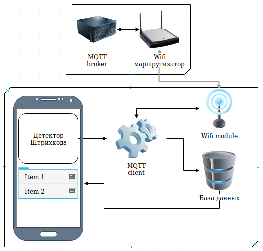
Based on the analysis of the requirements for the system, its structural diagram was compiled:
3.1. The algorithm of the application
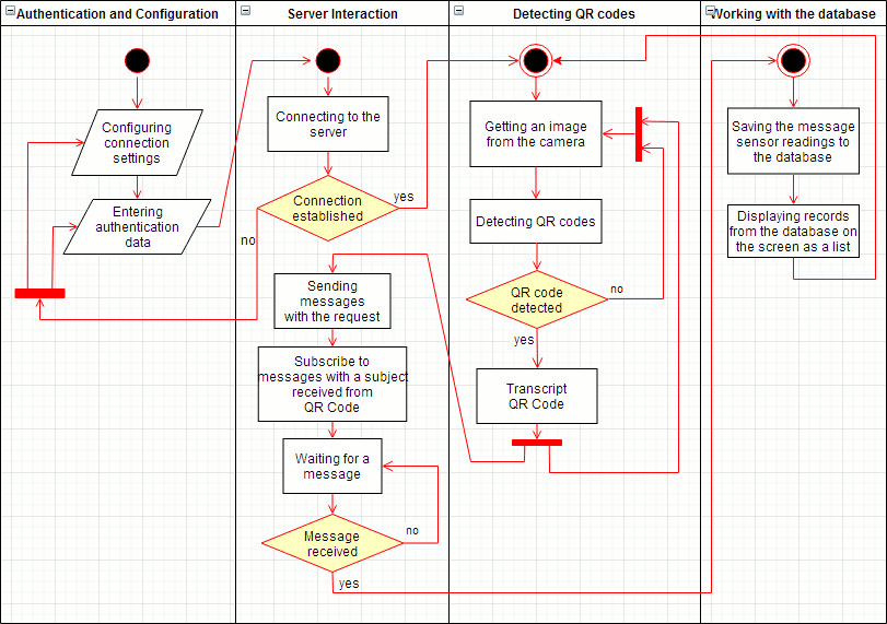
In the work of the application, there are four main stages:
- Authentication and configuration
- Interaction with the server
- QR code detection
- Working with the database
All the steps are presented in the block diagram:
3.2. Application Structure
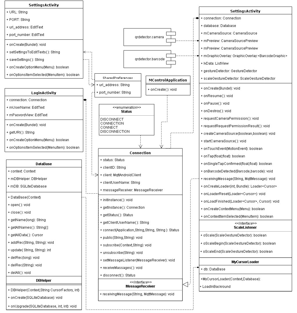
| Module | Implemented a function |
|---|---|
| MQTT | Connecting to the broker, authentication sending messages with a report on the identification of the sensor, receiving messages with the readings of the identified sensors |
| QRDecoder.Camera | Controlling the camera and getting an image from it |
| QRDecoder.Barcode | Detection and decryption of QR codes received in the form of camera images |
| Database | Interaction with the SQLite database |
| UI | Implementation of the user interface |
3.3 MQTT client
MQTT or Message Queue Telemetry Transport is a lightweight, compact and open data exchange protocol designed to transfer data to remote locations where a small code size is required and there are limitations on channel bandwidth. The above advantages allow it to be used in M2M (Machine-to-Machine Interaction) and IIoT (Industrial Internet of Things) systems.
To create the MQTT client in my app, I used Paho MQTT and Android service, provided by Eclipse. How to add it to the project and how to interact with it is viewed in the MQTT-client for Android.
3.4. Sensor identification
The sensor ID in the system will be the unique name of the sensor, which will be entered using the device’s camera. For image processing, Google specialists have implemented code examples android-vision, in which there is a module * * barcode-reader**, consisting of classes:
| Class name | Function to implement |
|---|---|
| CameraSource | Provides camera control for getting a preview. Receives the camera preview image at a certain frequency, sending the frames to the detector as it processes them. Frames can be discarded if the detector does not have time to process all the frames generated by the camera. The frame rate can be specified using the setRequestedFps (float) method. |
| CameraSourcePreview | Is responsible for displaying the camera preview frames on the screen. |
| GraphicOverlay | Displays graphical objects on top of the associated camera preview. A view that displays a series of custom graphics overlaid on top of the associated preview (i.e., the camera). Allows you to add graphic objects, update them, and delete them by calling and disabling the visibility of the corresponding drawing within the view. Supports zooming and mirroring graphics relative to the camera preview properties. The element sizes are expressed in preview size values, but must be scaled to the full screen size. |
| BarcodeGraphicTracker | This is a tracker that is used to detect barcodes on the screen, and track them to overlay graphics, as well as delete graphics when the barcode leaves the field of view. |
| BarcodeGraphic | Used to draw an instance of an image superimposed on a barcode, taking into account its position, size, and ID. |
| BarcodeTrackerFactory | Implements the “Factory” pattern and is used to create barcode trackers-one for each barcode. |
These classes use the Mobile Vision interfaces, which provide an API for barcode detection. At the moment, this library is already outdated and not supported, you can use the ML Kit library instead
3.5. Storage of information
The information stored in the app is divided into two groups:
- Camera settings(backlight, autofocus) and connection settings
- Sensor readings
The first group is characterized by a small but constant amount of data. Therefore, it will use SharedPreferences as its storage-a permanent storage on the Android platform used by applications to store their settings. The following fields will be created in the SharedPreferences file:
<map>
    <string name="Ключ">Значение</string>
</map>
The keys and parameter values will be set at the start of the application and stored in a private storage. You plan to use the following keys:
-
autoFocus — responsible for the use of autofocus, takes the values:
ON — autofocus is activated
OFF — autofocus is deactivated
-
useFlash — it is responsible for turning the camera’s backlight on / off, and takes the following values:
ON — the camera light is on
OFF — the camera light is off
- url_address — corresponds to the value of the server url
- port_number — corresponds to the value of the port number
The second group — sensor readings-is very dynamic during operation and can both increase the amount of data used in the application and reduce it. The application uses an SQLite database to store information about sensor readings.
The application database will consist of three tables:
- types — contains the main types of sensors
- sensors — contains the unique names of the sensors
- readings — stores sensor readings

In the types table, in addition to the id field, which is the primary key, there are four other fields:
- type_neme — текстовое поле с названием типа датчиков
- unit_of_measure — текстовое поле с названием единиц измерения
- upper_limit — информация о верхней границеизмерений, тип real
- lover_limit — информация о нижней границеизмерений, тип real
В таблице sensors, помимо поля id, которое является первичным ключом, имеются три поля:
- sensor_name — a text field with the name of the sensor type
- unit_of_measure — foreign key, the corresponding id from the types table is required to match the sensor and the units of measurement corresponding to this sensor type
- detection_time — the time of detection and recognition of the sensor, it is necessary to sort the data when output in the INT(long).
The third table reads also contains the id field(primary key), and three fields:
- sensor — foreign key, corresponding to the id from the sensors table
- value — stores the value received from the server
- time — contains the time value since the last update of the value
3.6. Graphical user interface
Four functions are expected for direct user interaction: authentication, setting up a connection to the server, identifying sensors and visualizing their readings. Based on this, the navigation map of the application was compiled:
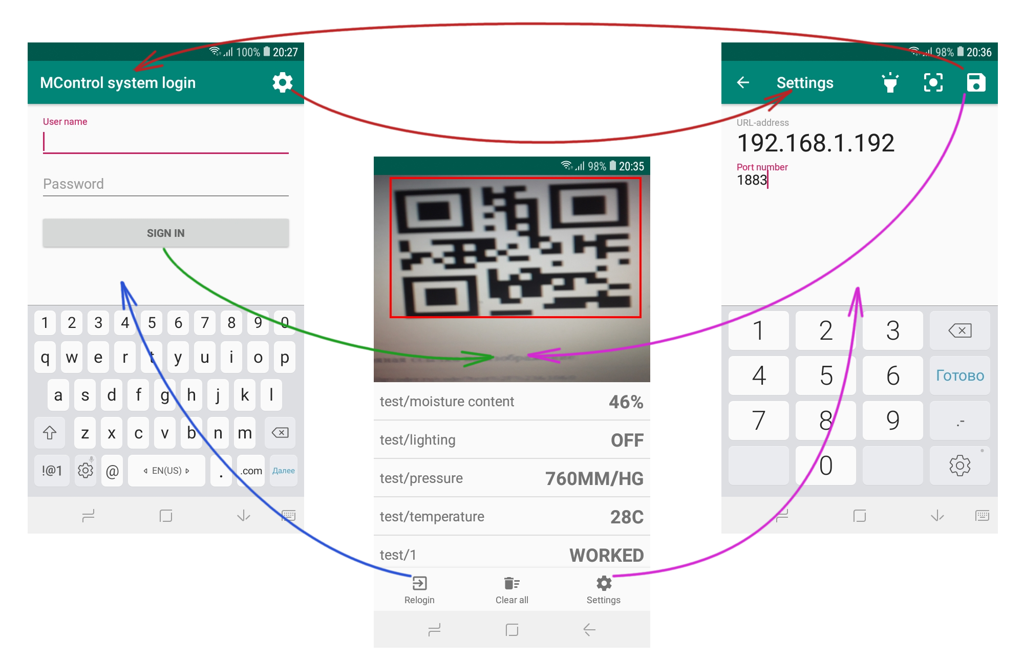
The authentication screen contains text fields for entering the user name and password, which are used to authenticate the user in the system, the «Sign in» button, which attempts to connect to the server, and a virtual keyboard for entering values in the text fields. Also in the top menu there is a button to go to the settings screen, designed in the form of a gear icon. If after clicking on the «Sign in» button, the connection to the server is not established, an error message will be displayed on the screen with a suggestion to check the connection settings. To set up the connection, click on the gear icon in the corner of the screen. This will take you to the settings screen.
There are also two text fields on the settings screen:
- A field for entering the URL.
- Field for entering the port number.
The virtual keyboard depends on the active text field. If the URL field is active, a full keyboard with basic alphanumeric elements is displayed. If the port number field is active, only the numeric keypad is displayed. The following items are activated in the top menu:
- «Back arrow» — implements a return to the previous screen.
- «Lighting» — activates the backlight using the camera (if supported by the device).
- «Autofocus» — activates the camera’s autofocus mode (if supported by the device).
- «Save» — saves the entered settings.
The main screen of the app combines a sensor identification area and a list. To identify the sensor, an image from the camera is used, which the user directs to the QR-code. The list of identified sensors is displayed below, in reverse order of the identification time. Each item in the list contains the name of the sensor and its readings.
At the bottom of the screen there is a horizontal menu, which consists of the following items:
- «Relogin» - go to the authentication screen
- «Settings» - go to the settings screen
- «Clear all» - delete all records and disable requests
In addition, special movements allow you to adjust the zoom on the camera, and a long press on the list item opens the context menu, through which you can delete this item.
4. Testing
To check the health of the application, you will need:
- A computer with the ability to connect to a network and a network OS;
- WiFi Router;
- MQTT-broker;
- Script for modeling the generation of sensor readings;
- QR codes with sensor names encrypted in them.
4.1. Installing the MQTT Server
To organize the transmission of messages over the network, you need to install Mosquitto – this is a popular MQTT server (or broker). It is easy to install and configure and is actively supported by the developer community. Installing the Mosquitto using the console command:
sudo apt-get install mosquitto-clients
By default, the Mosquito service starts immediately after installation. To set up a password in the console, enter:
sudo mosquitto_passwd -c /etc/mosquitto/passwd <username>
Opening the configuration file:
sudo nano /etc/mosquitto/mosquitto.conf
In the file that opens, you must specify the path to the file with the user name and password hash:
allow_anonymous false
password_file /etc/mosquitto/mosquitto.pwd
After saving the file, you need to restart the server:
sudo systemctl restart mosquitto
4.2. Script for generating test values
To simulate the system operation, a script was written in the bash language. In an infinite loop, the script generates random values and sends them to the server using the mosquito_pub command, which redirects these messages to clients who have subscribed to the corresponding topics.
#!/bin/bash
echo "Restart the server"
sudo systemctl stop mosquitto
sleep 0.5
sudo systemctl start mosquitto
sleep 0.5

echo "Getting the server address"
ipm="$(ip -4 addr show scope global | awk '$1 ~ /^inet/ {print $2}')"
ip="$(echo $ipm | awk -F"/"'{print $1}')"
echo "ip = "$ip

echo "Starting the value generation cycle"
echo "-----------------------------------"
n=32
i=0

while [ 1 ]
do
    let "number = ($RANDOM % 100)"
    number=0.7$number
    number+="Bar"
    mosquitto_pub -h $ip -t "Company/Engine-room/oil-pressure" -m $number -u "8host" -P "1234"

    let "number = ($RANDOM % 10 + 1495)"
    number+="об/c"
    mosquitto_pub -h $ip -t "Company/Engine-room/revs" -m $number -u "8host" -P "1234"

    let "number = ($RANDOM % 10)"
    number=34.3$number
    number+="С"
    mosquitto_pub -h $ip -t "Company/Foundry-Shop/temperature" -m $number -u "8host" -P "1234"

    let "number = ($RANDOM % 10)"
    number=2.5$number\
    number+="м/с"
    mosquitto_pub -h $ip -t "Company/Assembly-line/speed" -m $number -u "8host" -P "1234"
done
4.3. QR-codes
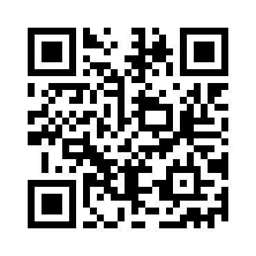
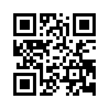
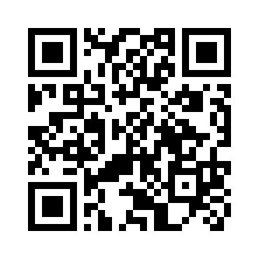
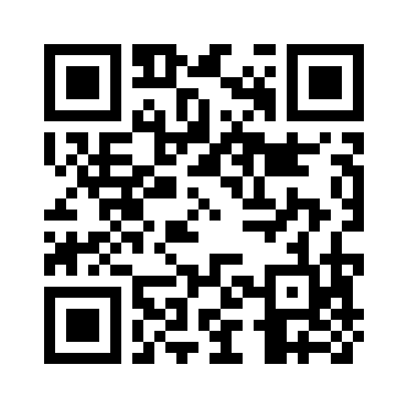
To check the functionality, the corresponding QR-codes were generated:
Thank you for your interest! :)
